An alternative headline is: “how to show your wife how much you love her, the geek way”.
From 17 to 22 of September I was in New Orleans participating in the discussions of the Linux Plumbers Conference, which has already turned into one of my favorite conferences. Lots of fun, talking to great people and good discussions about systemd, containers, cgroups, kernel modules, etc. However as the headline indicates this blog post is not to talk about the conference but rather about a toy the Intel booth was giving out: a fan with 7 leds in its propeller. See below:
 Fan distributed to attended during LPC
When turned on it shows a text message: “We’re hiring!”, “01.org/jobs”. So, if you are looking for a job and want to come to work with me, you already know where to apply ;-). The fun part is that in its box it’s written “programmable message fan”. The guys from the booth told me that the first question people were asking was how to change the message appearing there, but they had no idea. This post is to show how I did that.
Some days after arriving in Brazil I saw a post from Steven Rostedt on G+ regarding this fan and a blog post he found: http://hackingwithgum.com/2009/10/06/hacking-the-cenzic-pov-fan/. Disassembling our fan showed that it’s a little bit different than that one, changing the EEPROM and with 1 extra pin.
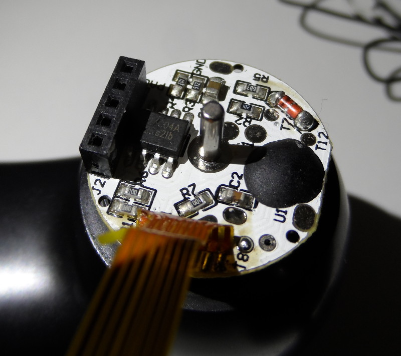 Disassembling the fan
However looking carefully at the board we can see it’s pretty similar: It’s a T24C04A EEPROM that is programmable via I2C. I’m not sure if the extra pin is the the write-protect feature that is present in this EEPROM or if it’s to select the address (in which case we would just have another address on our side). Hence we are safe connecting it to ground. From T24C04A’s datasheet we figure it can work in the range 1.8V to 5.5V. So, instead of using a serial connector like in the other blog post, we can use any development board that has an I2C bus available for us to play with it, particularly BeagleBone Black that has a 3.3V I2C bus, which I’m using here. From the picture below you can notice that a) I didn’t have many HW components available and b) my drawing skills are horrible. I just did a quick hack to get it to work, i.e.: connect GND, VCC and the pull-up resistors (since in I2C the bus is high when nobody is transmitting) [ See UPDATE 2 ].
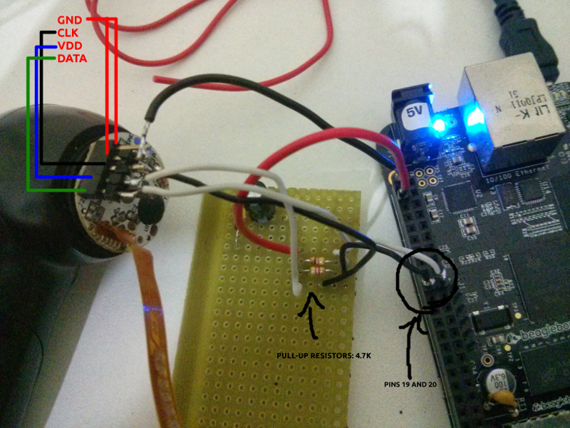 Wiring the fan to beaglebone
For reading from and writing to the EEPROM I’m using i2cdump and i2cset respectively. And i2cdetect to show me where the device was plugged and its address. Beware that in beaglebone the devices in /dev don’t match the ones in the HW schematics (thanks Koen for pointing out this to me).
Now the software part. Like in the other fan we have a column of 7 leds and each letter is “rendered” using 5 rows. However the way the strings are written is different. I tried to use the python script that was provided, but after some tests I figured I’d need to do some modifications. Below is how the strings are stored in our fan’s EEPROM:
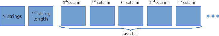
First byte is the number of strings present in the EEPROM. Each string then has as its first byte the string length. Then we have 5 bytes for each char, in reverse order. They encode the state of the LEDs in each column: 0 means ON and 1 is OFF. After some try and errors we realize that not only the string is reversed, but also the columns. So the first byte in the character encodes the right-most column. In the end we have a 7x5 matrix for each char. I started to draw all chars and change the python script to use them, ~~but I got lazy and just finished the letters I was interested in~~ (see UPDATE 1). The final result is the video shown above that says “Talita, I love you”, in Portuguese :-).
I used the following commands to dump the EEPROM, encode the text and write to it.
root@beaglebone:~# # dump what's in address 0x50 on bus 1 (use i2cdetect to find out the bus and address of your device)
root@beaglebone:~# i2cdump 1 0x50
root@beaglebone:~# # encode the message given as args
root@beaglebone:~# /tmp/ascii2fan "string1" "string 2 with space" "string 3" > ~/message.bin
root@beaglebone:~# # write the content of ~/message.bin into the EEPROM
root@beaglebone:~# i=0; od -An -t x1 ~/message.bin | while read line; do
                  for c in $line; do
                      cmd=$(printf "i2cset -y 1 0x50 0x%x 0x$c b" $i); $cmd; ((i++));
                   done;
               done
You can download my modified ascii2fan. I was using it on /tmp and lost it after power cycling, so I needed to change the file again and I didn’t confirm it’s still working. It’s almost the same as the one provided in hackingwithgum.com, it’s just the table that really changes.
UPDATES:
- I uploaded a new version of ascii2fan, containing all the letters.
- As Matt Ranostay pointed out, the beaglebone black has already an internal pullup resistor, so this is not really necessary.